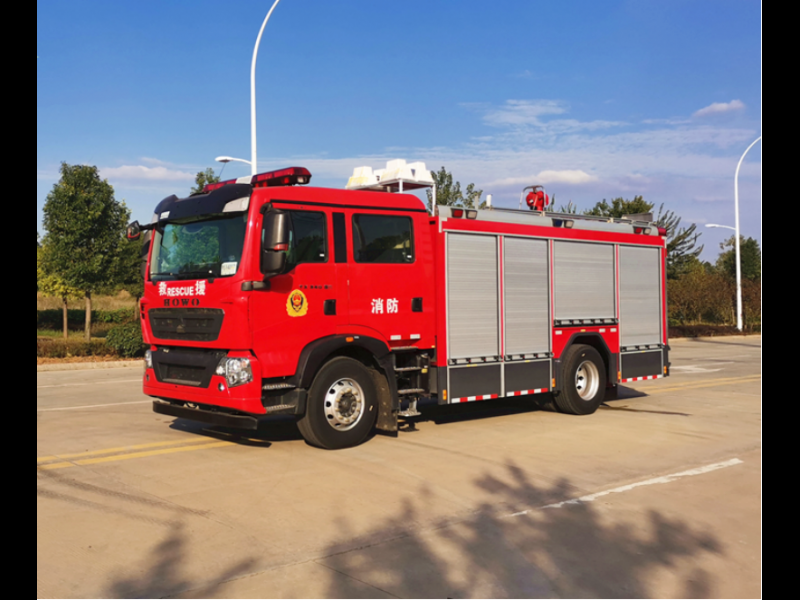
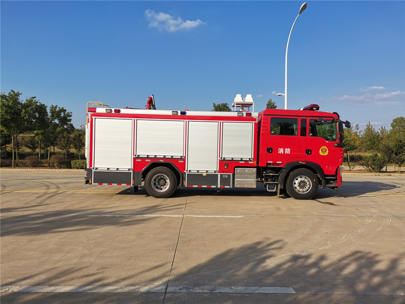
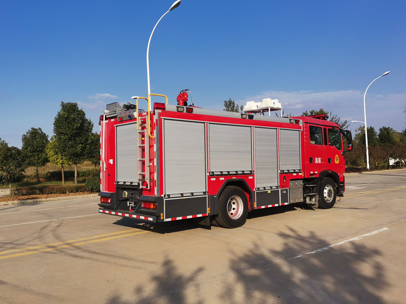
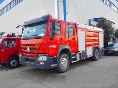
Main parameters of vehicle
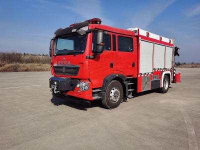
Ø Exterior dimension:8300x2500x3430mm
Ø Gross vehicle weight:15500kg
Ø Liquid carrying capacity:Tank volume is not less than 5000L
Ø Rated flow of fire pump:60L/s @1.0MPa; 30L/s @2.0MPa;
Ø Fire gun flow:60L/s 1.0MPa
Ø Fire gun range: ≧60m (water), ≧55m (Class B foam), ≧35m (class A foam)
Ø Front winch parameters:Tension:75.6KN;Drive type: electric
Ø Lifting light parameters: Ground height:≥7.6m
Main parameters of compressed air foam system
|
|
Wet foam |
Dry foam |
||||
|
Flow rate (L/Min) |
Range (M) |
Foaming ratio |
Flow rate (L/Min) |
Range (M) |
Foaming ratio |
|
|
Exit A |
180 |
≥22 |
≥7 |
100 |
≥12 |
≥10 |
|
Exit B |
180 |
≥22 |
≥7 |
100 |
≥12 |
≥10 |
|
Gun outlet |
280 |
≥22 |
≥7 |
|
|
|
|
Gun outlet (Extra wet foam) |
480 |
≥35 |
≥6 |
|
|
|
Main parameters of chassis
Ø Type: ZZ5207TXFV471GF5, SINOTRUK HOWO Euro Ⅵ chassis
Ø Drive type: 4×2
Ø Wheel base: 4700mm
Ø Speed: 101km/h
Ø Engine type: MC07.34-60
Ø Power rate: 248kW
Ø Total mass: 20100kg
Main structure
Ø Cab
1.Structure: T5G-S four-door cab with 2+4 passengers.
2.Seat setting: 2 people in the front row and 4 people in the back row, among which 4 air breathing apparatus fixed racks are set behind the rear passenger seat, and there are exquisite safety railings at a height of 1.2m in front.
3.Flip: forward flip electric lift flip system (come with the original car).
4.Occupants indoor equipment: In addition to the original equipment, equipped with 100W alarm, switch, force switch, indicator light.
5.Lights: Long row of LED stroboscopic red mounted on top of cab.
Ø Container:
1. Liquid carrying capacity:
a. Tank load: 4000kg
b. Class A foam tank liquid load: 300kg
c. Class B foam tank liquid load: 700kg
2. Material:
a. The water tank is welded with high quality carbon steel plate
b. The foam tank is welded with high quality stainless steel plate 0Cr18Ni9
c. Water tank structure: the water tank is welded structure. The front and rear sealing plates, the two side wall plates of the tank and the vertical and horizontal defense plates are provided with trapezoidal folding tendons that can increase the strength. There are also maintenance manhole ring and anti-water vortex turbulence structure.
d. The top of the tank has an entrance hole, with a quick locking and opening device can cover.
e. The tank top is connected with a Φ80 mm overflow pipe valve structure.
f. 1 level indicator.
g. 1 sewage outlet.
h. Class A foam tank structure: located at the top of the front of the water tank, with a partition reinforcement.
i. The tank top is provided with A class A foam injection port.
j. The tank top is provided with an air outlet.
k. A low liquid level protection switch is set at the bottom of the tank.
l. 1 level indicator.
m. The bottom of the tank is provided with a sewage discharge outlet.
3. Class B foam tank structure: located in the front of the water tank, its strength is safe, reliable sealing.
a. The tank top is provided with a type B foam injection port.
b. The tank top is provided with an air outlet.
c. The bottom of the tank is provided with a sewage discharge outlet.
d. 1 level indicator.
Ø Water pump
1. Water pump:
a. Model: CB10.20/30.60 medium and low pressure fire pump
b. Rated flow: 60 L/[email protected]; 30 L/[email protected]
c. Material: Aluminum alloy shell, stainless steel pump shaft, copper alloy impeller and seal ring, chrome-nickel alloy gear
2. Primer water pump:
a. Piston suction depth: ≥ 7m
b. Pilot time: ≤ 50s
Ø Class B foam proportional mixing system:
1. Foam ratio mixer Model: PH64
2. Type: negative pressure ring pump type
3. Mixing ratio: 3-6%
Ø Compressed air system: DC- CAFS60/45m
1. Air compressor model: EV06-NK
2. Type: screw type
3. Rated flow rate: Rated performance 5.5m³/min, (pressure 0.85MPa)
4. Working pressure: 0.85Mpa
5. Maximum working pressure: 1.5MPa
6. Automatic pressure balancing system: pressure fluctuation range with water pressure ≤10%
7. Electric foam pump model: BM12.10N
8. Flow and pressure: 12L/min/0.8Mpa
9. Proportional adjustment range: 0-9.9%
10. Maximum injection pressure: 1.4Mpa
Ø Piping system
1. Suction pipe
a. Set up a water suction piping system in DN150 tank.
b. A DN150 external suction pipe system is provided at the rear of the water pump.
2. Compressed air foam pipeline:
a. One DN65 and DN80 compressed air foam outlet is set on the left side of the pump room.
3. Water injection line
a. There is one DN65 external water injection port installed on the right side of the carriage, which can inject water into the tank through the pipeline.
b. A DN65 pipe is installed in the pump house to fill the tank and pass through the DN65 ball valve.
4. Water outlet pipe
a. The top of the vehicle is equipped with a DN80 fire gun pipeline and valve.
b. One DN80, DN65 outlet pipe and control valve are set on the left and right sides of the pump house.
5. Residual water pipe:
a. The bottom of the compressed air foam system is provided with a discharge pipe and a control valve.
b. The bottom of the water pump is provided with a discharge pipe and a control valve.
6. Cooling water pipeline
a. In order to make the air compressor and force extractor run normally, the cooling water pipeline and control valve connected with the air compressor cooling system and force extractor cooling system are equipped.
7. Blow-off line :
a. A DN40 blow-off line and control valve are arranged at the bottom of the tank.
b. A DN25 blow-off line and control valve are arranged at the bottom of Class B foam stock liquid tank.
c. One DN25 blow-off line and control valve are arranged at the bottom of each class A foam stock liquid tank.
Ø Fire cannon
1. Model: PL8/48 foam/water fire cannon (compressed air foam can be produced by replacing the A gun head)
2. Location: top of tank
3. Mode: Manual
4. Injection pressure: 0.8Mpa
5. Flow: 48L/s
6. Rotation Angle of jet gun: 360°
7. Elevation of injection gun: ≥+75°
8. Injection gun depression: ≤-15°
9. Range: Water ≥70m foam ≥60
Ø Lifting lighting system
1. Generator: Honda Power
2. Power: 10.5KW
3. Frequency: 50HZ
4. Voltage: 220V
5. Main lighting:
6. Power: 4×1000W
7. Mobile lighting: 500W/ 2 PCS
8. Lifting rod:
a. Type: pneumatic
b. Height from the ground: 8m
c. Lifting weight: 45kg
9. The head of the cloud:
a. Pitch: 330°
b. Horizontal rotation: 360° full rotation
c. Voltage: 220V
10. Cable tray:
a. Voltage: 220/380V
b. Frequency: 50HZ
c. Quantity: 30m (220V) x2
d. Distribution box: equipped with functional control keys, instruments, all kinds of operations are concentrated on the control box, and can accurately and quickly control all the operation of the operation, equipped with 5m wire control button.
Ø Traction winch System: (US CHAMPION)
1. Type number: N16800XF
2. Drive form: DC electric
3. Tensile force: 7650Kgs
4. Wire size: 13mmx38m
5. Weight: 108kg
6. Installation position: located at the rear of the vehicle
Ø Force extractor:
1. Type: sandwich type
2. Control: Solenoid valve, pneumatic control, control position is located in the cockpit instrument panel
3. Cooling method: oil cooling
4. Lubrication mode: splash lubrication
Ø Equipment box and pump room:
1. Material: The main skeleton of the body is steel profile, and the internal equipment frame is aluminum alloy profile. The interior side plate is 1.2mm aluminum oxide pattern plate, and the interior bottom plate is 1.2mm aluminum oxide pattern plate.
2. Structure: The use of steel frame and aluminum alloy profile special connector structure, sufficient space for placing equipment, placing equipment partition space can be adjusted. Appropriate location selection using vertical pushed shelf, cutting plane and air respirator spinning frame, guarantee the equipment is easy to access. For the parts inside the carriage that need to be inspected frequently, a valve is installed in the appropriate part, and other places that need to enter the interior of the car for inspection and maintenance are also equipped with open or movable plates.
3. Rolling shutter door: All equipment boxes and pump rooms are using rolling shutter doors with locks. The handle and lock are durable and should not be deformed. The guide rail of the rolling shutter door is equipped with LED lighting belt, and all the rolling shutter doors have been tested for water shower sealing performance.
4. Turning foot: steel frame covered with aluminum alloy pattern plate, using hinge and stop double locking, foot pedal corner installed with yellow warning light flashing, safe and reliable.
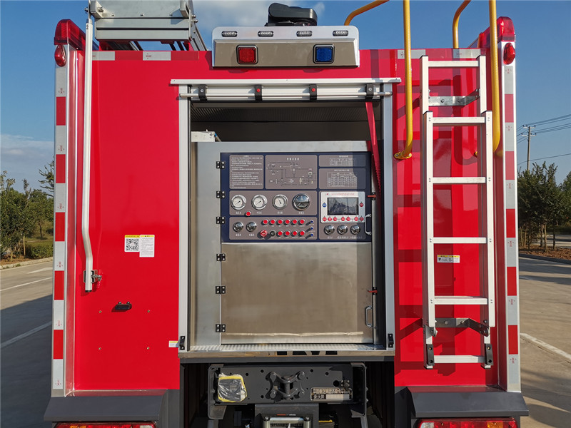
Ø Instrument panel and equipment on board
1. The instrument panel is located in the pump room at the rear of the vehicle with a control panel and adequate lighting; All control handles, switches and indicators are marked with instructions on how to operate them.
2. The instrument panel is equipped with:
a. Liquid level gauge: 3 pieces
b. Tachometer: 1 piece
c. Pressure gauge: 1 piece
d. Vacuum pressure gauge: 1 piece
e. Foam proportional mixer control unit: 1 set
f. Air compressor thermometer: 1
g. Throttle adjustment device: 1 set
h. Instrument lighting switch: 1 PCS
i. Air pressure gauge: 1 PCS
j. Class A water supply switch: 1
k. Gun control switch: 1
l. Other types of control valves
Ø Electrical and Warning Systems
1. The total power of all electrical equipment in the vehicle is less than 1.4 times the rated power of the generator.
2. License lamp holder meets the requirements of GB4785 and meets the lighting requirements of license plate.
3. The top of the cab is equipped with a 1.6-meter LED long row stroboscopic red alarm with alarm power of 100W; The alarm and flash circuit are control additional circuits, and the alarm is installed in the driver‘s room.
4. Blue and red flashing lights are installed on the left and right sides of the top of the car, with an interval of no more than 3m. Four safety sign lights and side recovery reflectors (combined type) are installed on the lower sides, with front and rear profile lights, and a turn signal on both sides. Lighting devices are installed in the cab, equipment box and pump room, which comply with the regulations of GB4785.
5. The system control panel at the rear pump room is equipped with various indicators, display instruments and safety alarm devices.
6. The automatic charging system is installed in the appropriate position of the vehicle to automatically charge the vehicle battery intelligently when the vehicle is stopped, so as to avoid starting difficulties caused by power loss.
Ø Spray painting
Adopt domestic paint, cab, car body is fire red, chassis and sub-frame is black, fender, bumper, small high top is gray. Vehicle paint film requirements smooth, bright.
Ø Overall technical requirements
1. The vehicle performance conforms to the provisions of GB7956.1-2014 Fire Engine Part 1: General Technical Conditions.
2. The vehicle performance conforms to the regulations of GB7956.6-2015 Fire engine Part 6: Compressed air foam Fire engine.
3. Fire pump performance in line with GB6245-2006 fire pump provisions.
4. The external dimension, axle load and mass of the whole vehicle shall comply with the regulations of GB1589-2016 Limits of Road Vehicle External Dimension, Axle load and Mass.
5. The vehicle external lighting and signal devices shall comply with the GB4785 Installation Regulations for External Lighting and Signal Devices of Automobiles and Trailers.
6. All welding firm, smooth, smooth.
|
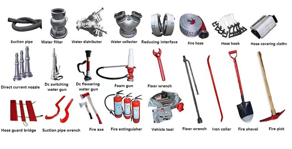
Vehicle Equipment |
|
|
|
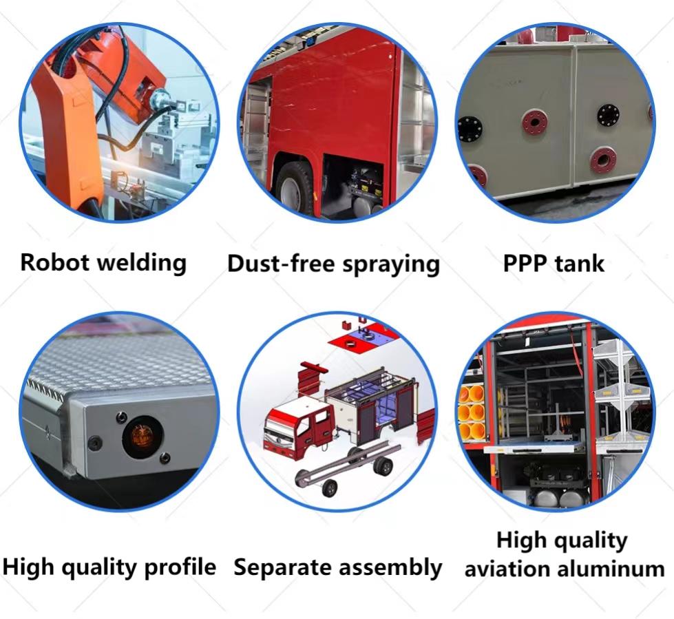
Details and advantages |
|
|
|
Purchase Process |
|
|


